3. Starting Risers and Wiring.
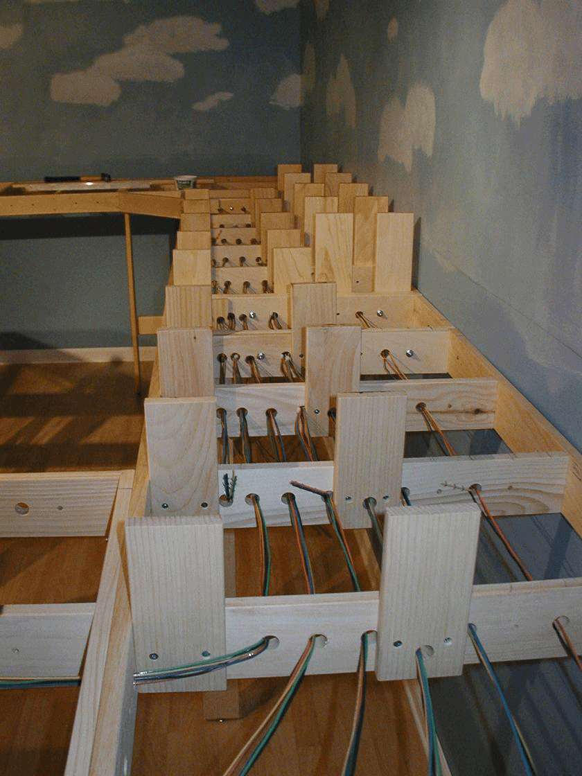
This photo is essentially the same as Photo Number 1. Broken Bow Yard on the lower level and Calgary on the upper lever in the corner. This is a good example of the track buss wiring from the BDL168's. Each bundle of 5 wires represents a Detection Zone of a BDL168. The black wire is common from the Booster, Green is the first detection section of each zone, yellow Number two, blue three, and orange four. The Zone identification tags are not on these wires at this stage, but each bundle is tagged every other bench section as to their BDL168 addresses. When dropping track wires to their buss, it makes it very easy to identify without tracing back to the source.
|

4. Main Power Supply.
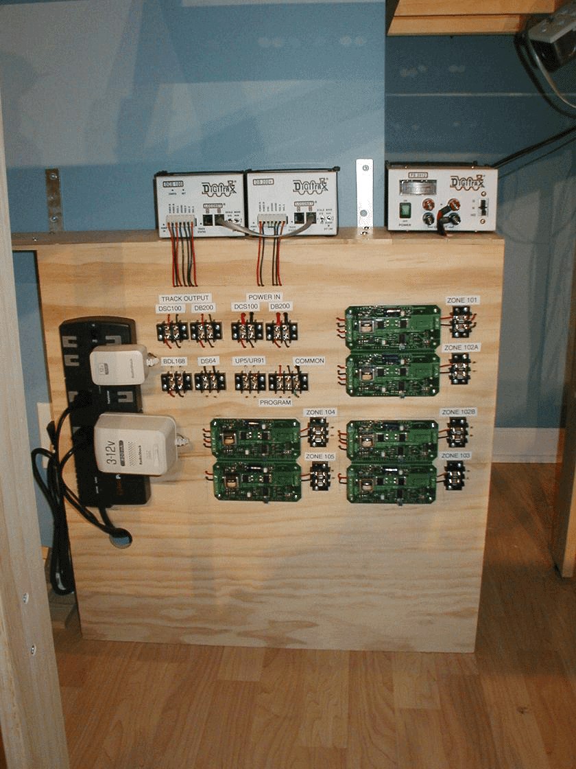
On the top shelf is the DCS100 Command Station, the DB200 Booster, and the PS2012 Power Supply. These supply the 2 Power Districts.
On the lower faceboard are various transformers (wall warts) and 6 of the DCC Specialties PSX1 Circuit breakers. This center supplies 6 of the eight Power Subdistricts.
|