Home          Table of Contents


1. Power Supply Panel.

This photo shows how the power is distributed to the layout. It is a 1/2 inch piece of plywood. The wires are connected to screw terminals and passed to the layout and equiment through holes in the plywood.  The PS515 and the PS315's each have a power buss of #14 single strand wire covering the complete layout. The PS515 supplies power to the DS64's and crossing gates and lights. One PS315 supplies the BLD168's and the SE8C's. The other PS315 supplies the UP and UR panels.

Equipment:
PS2012 (20 amp. Power supply)
PS515 (5 amp. Power Supply)
PS315 (2) (3 amp. Power Supply)
DCS100 (Command Station/5 amp. Booster)
DB200 (8 amp. Booster))
DCC Specialties PSX1's (6 shown)
(Circuit Breakers)


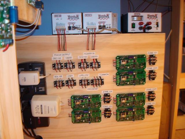
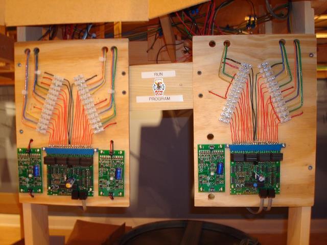
2. BDL168 Block Detector Wiring

This photo shows a BDL168 installation. The screw terminals were bought at Lowe's. The upper left two wires are from the power supply buss. The upper right wire is from the common buss of the Booster.  The curved red wires in the center portion are from the Red Track terminal of the Boosters. One side is from the DCS100 and supplies Detection Zones 1 and 2. The other side is from the DB200 and supplies Detection Zones 3 and 4.

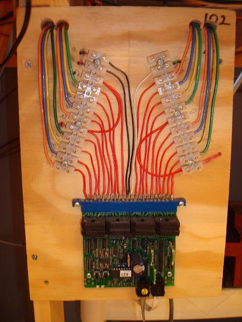
This photo is BDL168 Number 5 (board address 102) in the wiring diagram in Section I of the Home Page. It is the same as BDL168 Number 4 (board address 101). Both are fed by the DB200. It is the same as BDL168 Number 2 (address 104), except Number 2 is fed from the DCS100.

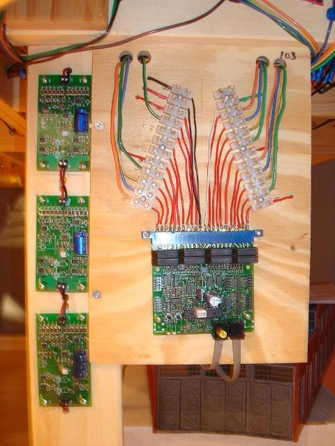
The detection sections are each bundled in groups of four #14 buss wires. After the bundle leaves the board it is joined with the appropriate Black Track terminal wire from the Booster. Therefore, there are bundles of 5 wires (track busses) that run under the tracks to which are connected the drop wires soldered to the track. These can be seen in one of the Layout Photos.

The first wire from each group of 4 is Green (detection sections 1, 5, 9, 13). Detection sections 2, 6, 10, 14 are Yellow. Detection sections 3, 7, 11, 15 are Blue. Detection sections 4, 8, 12, 16 are Orange. There is no reason for the color choce except that these are the colors sold at Lowes.


3. BDL168 Block Detector Wiring with Two Reversing Sections.

This photo shows BDL168 number 3 in the wiring diagram (board address 105) with two of the Detection Zones fed by a DCC Specialties OGAR (On Gaurd Automatic Reverser).

One reverser feeds Detection Zone 2 and the other feeds Detection Zone 4. Detection Zones 1 and 3 are fed directly for the Booster.

Detection Zone 1 and 2 are fed by the DB200 and Detection Zones 3 and 4 are fed by the DCS100.

Detection section 105-14 feeds Blaser Spur. Section 105-15 feeds Reverse Loop 4A and 105-16 feeds reverse Loop 4B. Section 105-13 is wasted.
All three blocks are part of the same reversing loop.

Section 105-6 feeds Reverse Loop 6 which is the passing Mainline for Blaser. Settions 105-5, 105-7, and 105-8 are wasted.

The remaining sections feed the Nimrod Spurs and portions of the Main Line.


4. BDL168 Block Detector Wiring with Three reversing Sections.

This shows BDL168 number 1 in the wiring diagram (board address 103) with three of the detection zones fed by a DCC Specialties OGAR (On Gaurd Automatic Reverser).

One reverser feeds Detection Zone 1. Another reverser feeds Detection Zone 2. The third feeds Detection Zone 3. The other Detection Zone is fed directly for the Booster. Detection Zones 1 and 2 are fed by the DB200 and Detection Zones 3 and 4 are fed by the DCS100.

Detection section 103-1 feeds Reverse Loop 3A. Section 103-2 feeds Reverse Loop 3B and 103-4 feeds Dos Vias Spur. Section 103-3 is wasted.  All three blocks are part of the same reversing section.

Section 103-5 feeds Reverse Loop 1A. Section 103-6 feeds Reverse Loop 1B. Section 103-8 feeds Destin Spur. section 103-7 is wasted.  All three blocks are part of the same reversing section.

Section 103-9 feeds Reverse Loop 2 which is a passing mainline for both Destin and Dos Vias.
Sections 103-10, 103-11, and 103-12 are wasted.  Sections 103-13 through 103-16 feed sections of the main line and Garrison Spur which is trackwork directly above the reverse loops.


5. DS64 Wiring

>

Each DS64 is powered from the DS515 buss with 2.1mm plugs. Turnouts are controlled by Tortoise Slow Motion Motors. Since I use computer control the DS64's are set to all 8 inputs as sensors.  On the Facia of the layout each turnout has a bipolar (red/green) LED and single pole double throw center off momentary on switch. (DPST MOM).

For each turnout there is a five wire cable to its appropriate DS64. The white wire is common and all connected to +COM. The Red and Green wires are connected to 1R and 1G (2R/G, 3R/G, 4R/G). The Brown and Black wires are connected to A1 and S1 (A/S2, A/S3, A/S4)

At the facia switch the White common is the center connection and the brown up and the black down. When the switch is toggled up or down, the DS64 sends a message to the computer. The computer interprets the message and sends a closed or thrown message back to the DS64. The turnout operates.  The advantage is that the computer checks to see that the turnout is clear, that the turnout is properly aligned for the train direction and that the turnout is not reserved already by another train. If all conditions are not met, then the turnout is not thrown.  This keeps visitors and grandkids from running switch points. The disadvantage is that the computer must be on and running RR&Co.'s Train Controller program. This is not a problem for me.

The red and green wires go through the LED to the turnout motor. The LED is Red when the turnout is thrown and Green when closed.  The Board addresses start with 11. Switch addresses start with 41. Sensor address start with 6-1,6-16 through 13-1,13-16. This keeps them from conflicting with the SE8C's and BDL168's.


6. SE8C Wiring

Each SE8C is powered from a PS315 buss along with the BDL168's. You must have computer control to use the SE8C (or some other method to compute the signal logic). I have 3 SE8C's controlling 73 3-aspect D-type signals. They are wired exactly as in the manual.

The board addresses of the SE8C's are 1, 2, and 3. Therefore, there is no conflict of addresses with the BDL168's and DS64's.


7. Program Track Switch

This is the four pole double switch (4PDT) for using the intergral programming track. The wiring diagram and description is on the Home Page Section I DCC Programming Track Drawing.


8. Homemade DCC LocoNet Distribution Panel

I bought all the parts and a good punchdown tool at Lowes and simply connected all the like terminals together on the back. To keep track of where everything goes, the upper left is always the incoming LocoNet Cable and the top right is always the outgoing cable to the next box. Two left is for throttles and only goes to UP5's. Some UP5's are daisy chained. Two right goes to DS64's. Some DS64 are daisy chained. Bottom left goes to BDL168's and SE8C's. Bottom right goes to anything else (computer) that needs a LocoNet signal. There are 10 of these around the layout.

Home          Table of Contents