Home          Table of Contents          Section I: Research and Equipment         Section II: Console Progress            Section IV: Console Construction Progress

Section III: Wiring Diagrams

Complete Wiring Diagram

Powering the Lexicon MX400 along with the Amplifiers and Speakers caused a loud POP in the speakers. To avoid this, I installed a Macromatic TR5022210 Timer Delay to turn on the Amps and Speakers after the Lexicon loads. It is set for 6 seconds.

Update April 2012: Diagram updated to show the addition of two MIDI Gadgets Boutique hwlcd-4's. Each one consists of two (2) lcd panels that each have two lines of 16 characters. This allows eight readouts of the Hauptwerk organs status. There are also one multicolor LED on each panel to indicate several status indications.

For example: one LED is programmed to turn from red to green when an organ is fully loaded and ready. Another is programmed ot turn from green to yellow to red if audio clipping occurs. Another turns from green to red when MIDI is recording and the fourth turns from green to red when Audio recording.

Update May 2013: Updated the sound card to the Focusrite Saffire Pro 40 and added the Lexicon MX400 Effects Processor.

Update August 2015: Diagram updated to show the addition of the Wireless MIDI for the Yamaha Clavinola.

Update October 2015: Diagram updated to show the Timer Delay Module to delay the Power to the Amplifiers. This avoids the loud pop in the speakers when the Pro40 and the MX400 power up and load the reverb effects.

The Focusrite Pro40 and the Lexicon MX400 are turned ON PRIOR to turning on the rest of the VPO to avoid loud pops in the speakers. They are also turned OFF AFTER the computer and VPO has been shut down for the same reason.

Below is de-cluttered wiring diagrams for clarity.

Wiring Diagram - AC Power Supply

Update August 2010: Diagram updated to show the additional MIDI wiring of two MIDI Gadgets Boutique hwwlcd-4's (4 2-line panels).

Update May 2013: Diagram updated to show the Focusrite Saffire Pro 40 and the Lexicon MX400 effects processor.

The Focusrite Pro40 and the Lexicon MX400 are turned ON PRIOR to turning on the rest of the VPO to avoid loud pops in the speakers. They are also turned OFF AFTER the computer and VPO has been shut down for the same reason.

Wiring Diagram - Audio/Video, MIDI and USB

Update August 2010: Diagram updated to show the additional MIDI wiring of two MIDI Gadgets Boutique hwwlcd-4's (4 2-line panels).

Update May 2013: Diagram updated to show the Focusrite Saffire Pro 40 and the Lexicon MX400 effects processor.

Updated August 2015: Diagram updated updated to show the Wirless MIDI transmitter. The wireless transmits to my Yamaha Clavinola Piano.

Update October 2015: Diagram updated to show the Timer Delay Module to delay the Power to the Amplifiers. This avoids the loud pop in the speakers when the Pro40 and the MX400 power up and load the reverb effects.

Rocker Tab Wiring

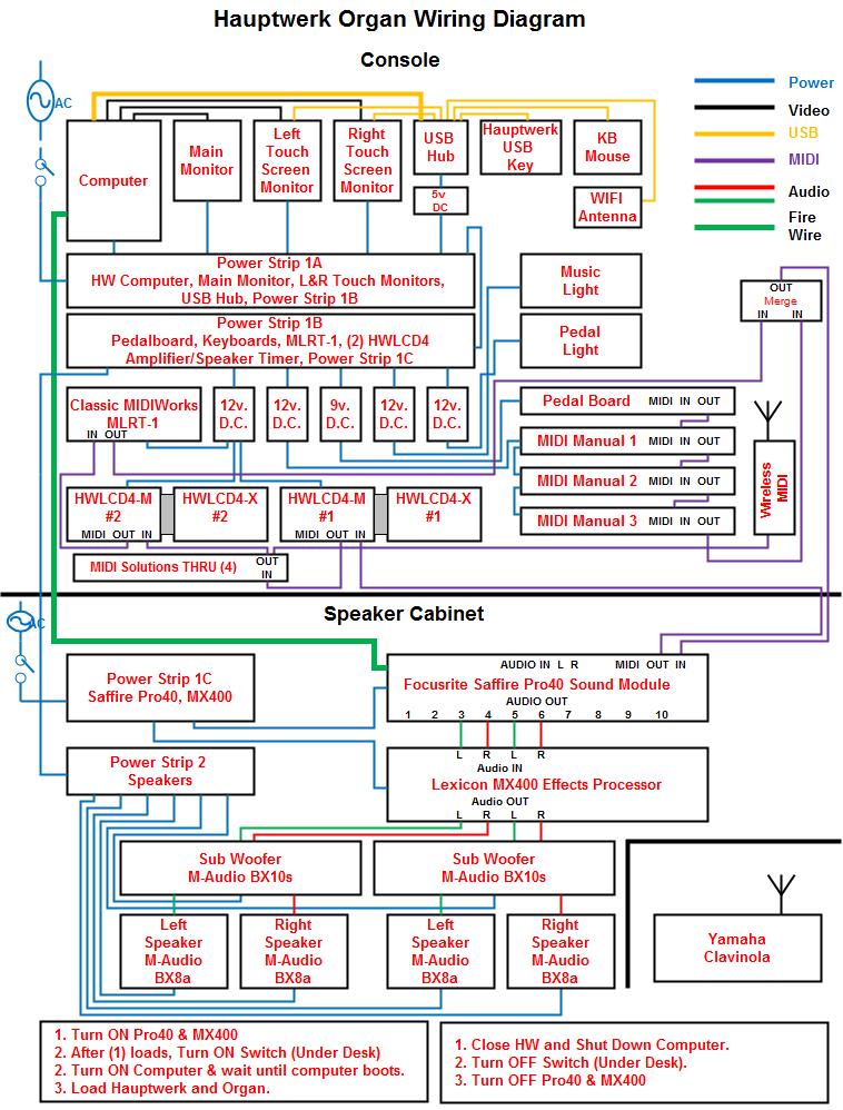
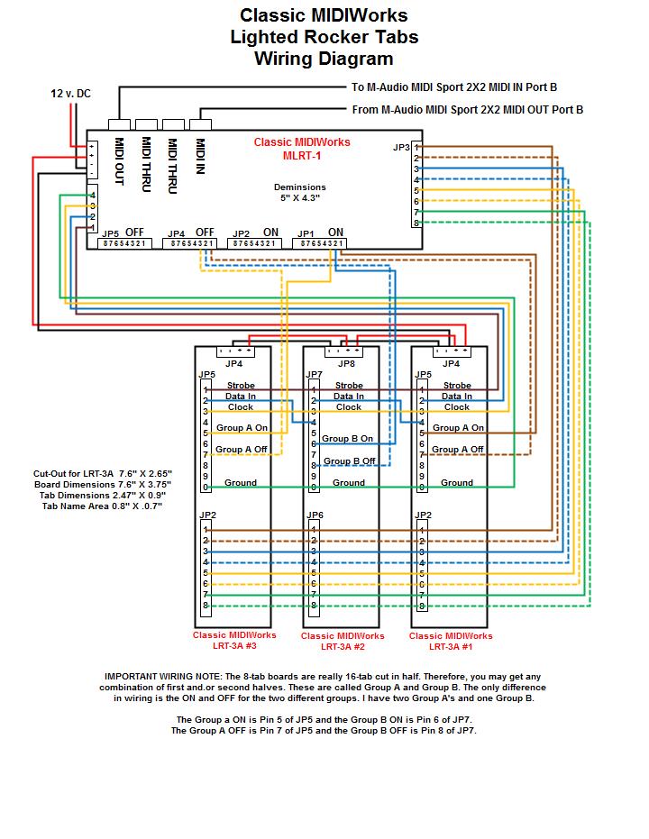
I ordered 4 - 8 tab LRT-3A's and 1 - MLRT-1 from Classic MIDIWorks. You can see how I installed them in the console section. The 8 tab boards are actually 16 tab boards cut in half. There is an A Group and a B Group on each 16 tab board. When wiring boards with 8 or less tabs, it is very important to know if you have an A or B Group. A Group boards can be identified with the power input located on one corner of the circuit board. The B Group power input is offset from one corner.

The A Group On/Off pins are pins 5 and 7 of pin block marked JP5. The B Group On/Off pins are pins 6 and 8 of pin block marked JP7. All other pins are the same on each board.

I took cat 5e wire and stripped the outer insulation off so that I had four pairs of multicolored wires. Classic sent me the connectors to attach to the pin blocks on the circuit board. They were of the punchdown type and the Cat5e wire was the exact size needed. As I attached the wires to the punchdown pins, I organized them into cables. These are seen in the console section.

UPDATE: With the addition of the LCD screens, I reduced the total lighted rocker tabs from 32 to 24 to make room for the mini-screens.

Home          Table of Contents         Section I: Research and Equipment         Section II: Console Progress            Section IV: Console Construction Progress