Home Table of Contents Section I: Research and Equipment Section II: Console Progress Section III: Wiring Diagrams
Console Construction
February 2011: The Nameboard is the first piece of the console to be constructed. It has 24 (3 groups of 8) Classic MIDIWorks LRT-3A's Lighted Rocker Tabs, controlled by their MLRT-1 lighted rocker tab control board. These are all couplers. I found that trying to touch the couplers on the touch screen while playing was tedious at best and wrong most of the time at worst.
LED screens from Midi-Boutique are mounted on each side of the rocker tabs.
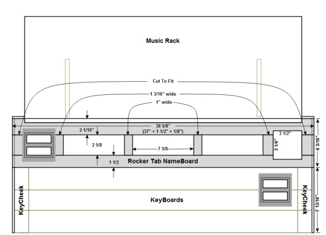
(1) Dimensional drawing of the nameboard.
|
The small pieces between the tab groups were cut at their respective locations so that the grain would better match. After glueing it together, it was surface planed to 5/8". The rocker tab boards were then mounted with 1/8" spacers.
The lettering was printed on Avery clear labels and cut to fit.
The square hole on each end are to accommodate the two sets of Midi-Boutique's hwlcd-4's. See next drawing.
|
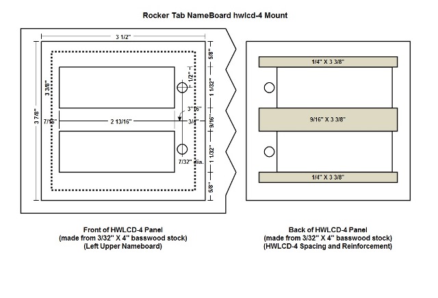
(2) Midi-Boutique's hwlce-4 mounting boards.
The hwlcd-4's are two lcd screens of two lines each. On the back I glued reinforcing strips that also served as spacers for the LCD screens.
|
(3) NameBoard assembled.
The NameBoard assembled before mounting the LCD screens and the lighted rocker tabs.
|
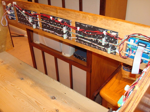
(4) Wiring of the lighted rocker tabs and LCD screens.
|
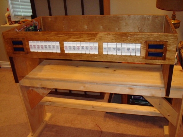
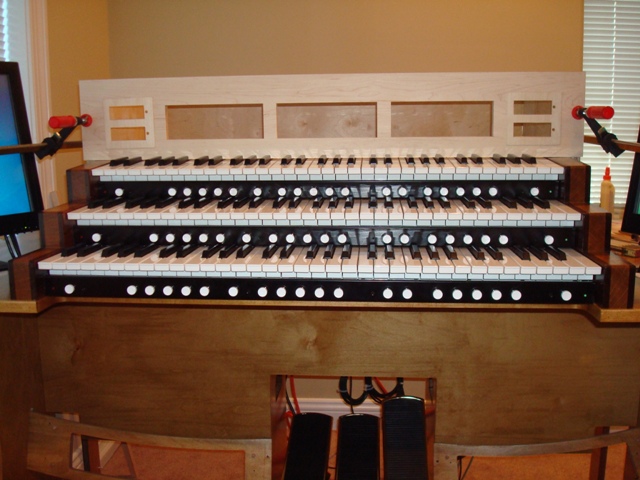
(5) Front view with lighted rocker tabs and LCD screens mounted.
|
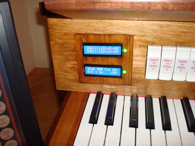
(6) Left LCD screens.
The top line shows the loaded organ and the second line shows the next cued organ. The 3rd line shows the current step number of the registration sequencer and the next cued step. If there are more manuals than three of the loaded organ, the 4th line shows the Division (SW or SO) of the top manual of the physical organ and the position of the corresponding expression pedal.
The top LED turns green when an organ is loaded and ready. The lower LED indicates audio clipping of the software output (green - yellow - red).
|
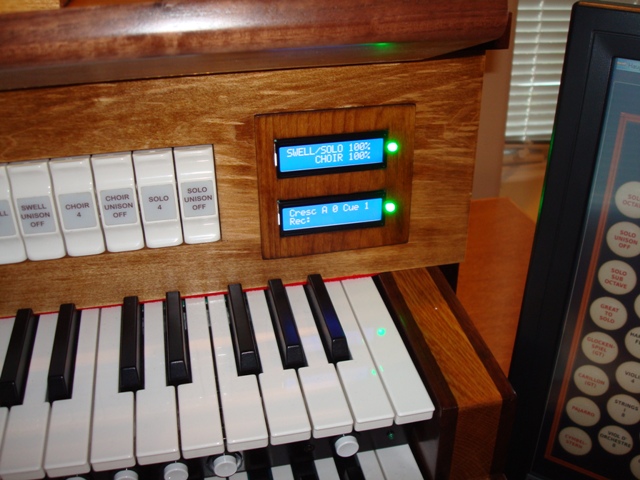
(7) Right LCD screens.
The top line shows the position of the expression pedal for the 3rd and 4th manuals (same pedal since there is only three). The second line showes the position of the Choir expression manual. On theater organs these show the position of the Main and Solo expression pedals. The third line is the Crescendo pedal position. The bottom line shows when MIDI/Audio recording is ON.
The top green LED turns red when MIDI recording is active and the bottom green LED turns red when Audio recording is active.
|
August 2011: Construction has finally began on the keycheeks. I do not have access to a router or shaper table, so I decided to make the keycheeks in pieces. Below is the method I chose. Since gluing three pieces of oak together left an obvious grain division on the upper surface of the keycheeks, I chose to use contrasting woods that actually emphasized this division. I chose walnut for the outer parts and white oak for the center. Below are the dimensions and pictures of the progress. After glueing all the parts together, I cut the bottom of the top two keycheeks to a 2 degree slant. Then I used a jointer to plane them down to fit the Classic CMK-2 Pro keyboards.
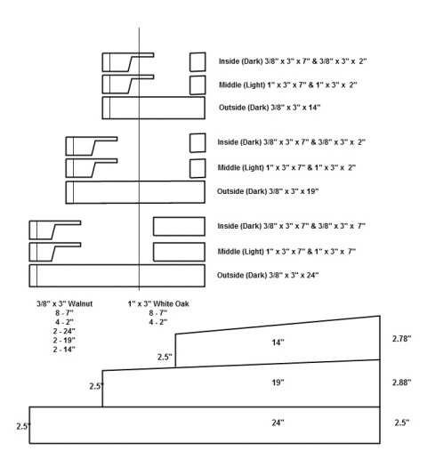
(1) Dimensional drawing of the keycheek parts.
|
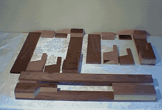
(2) Keycheek parts assembly.
At the bottom of the picture are the left and right lower manual keycheeks glued together and planed to size to fit. Above and to the left is the middle manual parts for the left side keycheek and the assembled middle manual right side keycheek before planing to size. To the right are the same parts for the upper manual. When all six keycheeks are finished they will be stacked and glued to a single piece on each side.
|
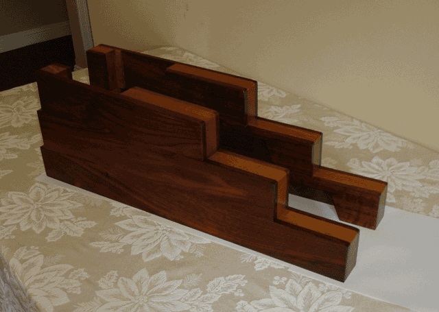
(3) Keycheeks assembled and finished.
|
October 2011: Construction has begun on the speaker cabinet. It will include 2 M-Audio SBX-10 sub-woofers and two pairs of M-Audio BX-8 speakers. The center poartion will house the regular computer speakers and the E-MU 1616m PCIe sound module.
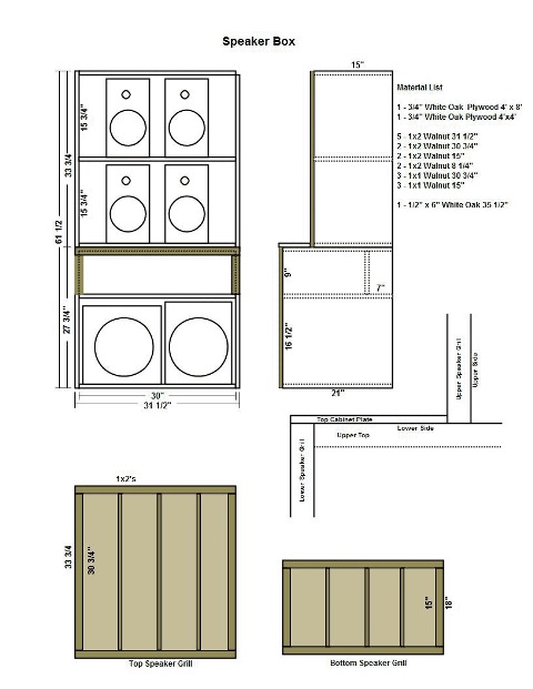
(1) Speaker Cabinet Drawing.
|
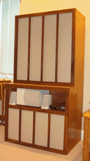
(2) November 2011. Speaker Cabinet Complete
|
Home Table of Contents Section I: Research and Equipment Section II: Console Progress Section III: Wiring Diagrams